


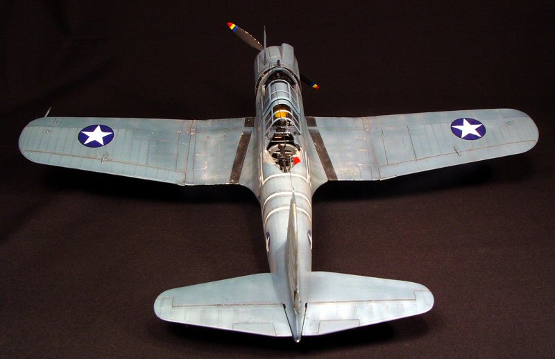
Accurate Miniatures 1/48 SB2U-3 Vindicator Build Review
By Kelly Jamison
| Date of Review | December 2005 | Manufacturer | Accurate Miniatures |
|---|---|---|---|
| Subject | SB2U-3 Vindicator | Scale | 1/48 |
| Kit Number | 480202 | Primary Media | Styrene, Photo-Etch |
| Pros | Boxing should be an industry standard. The false bottom with a beautiful side profile of the Vindicator should be taken out and framed for the modeling room. Cockpit detail is excellent. Weighted and un-weighted tire choice. Photo-etch seatbelts. | Cons | The infamous fuselage sink marks. Ejector pin marks on oxygen bottles. Instruction sheet confusing and inaccurate in places. Fit problems on a few parts. |
| Skill Level | Basic | MSRP (USD) | Out of Production |
Background
To read an In-box review click here.
Getting Started
Putting out a kit of this complexity is much like making a movie. Someone has to have the idea. Someone else has to lay the groundwork and do all the planning. Someone else has to execute and oversee the film being produced. Then in the case of making models someone else has to do the financing, engineering, instructions, boxing, decals, import problems, legal, on and on. Many hands must get involved. It is a very difficult endeavor and it is amazing that any kits get produced at all. Especially if you do not have the deep pockets of Hasegawa or Tamiya.
This Vindicator kit is a product of timing. Some good and some bad but nevertheless timing played a big part in the product you now have on the shelves. The warts in this kit have been well documented and the focus of this article is not to call them out again or reopen healed wounds but to show you how they can be overcome to make a really nice model.
With all model building, you need to get your research in line before starting the kit. The Vindicator is one of your more eclectic aircraft to build so information on it is limited. The “Vindicator In Action” by Squadron Publication is your best source of information. And as always a quick Google search will give you a lot of information to peruse at your leisure. If you can take a trip to the Pensacola Naval Museum to see the only existing Vindicator then you are miles ahead of most of us modelers. Many questions you have on how this plane is put together can be answered. After all, it is the source measurements for the Accurate Miniatures molds.
I like the format of the instruction sheet. Booklet style. The opening page has a small history lesson on the plane you are about to build. It also has a great little paint reference chart. I did not go through all colors and paints to check for accuracy so you might find an error here but I doubt it. I really like these paint matrix grids. They cover most major manufacturers and most of the colors you will need. Saves time and effort. It does not have a parts breakdown making finding parts difficult at times.
I read that the interior should be an unpainted aluminum color and I have read it should be a bronze green or dark green color. I choose an aluminum color thinking that the aircraft was built before the interiors were painted green from the factory. Had the plane gone through a depot (which they were scheduled to be after use at Midway) then the interior would have probably been painted green at this time. Educated guesses need to be used throughout the build. Your conclusions could easily be different.
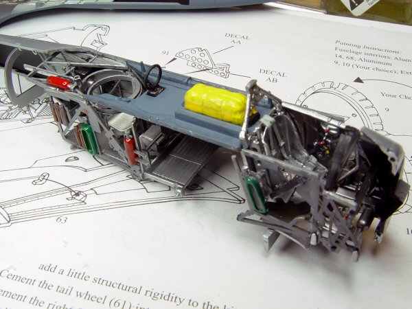
The main floor and back shelf, part #42 need a little bit of prep work. There were sink marks on the aft deck section so I filled in the large trench that the small radio/instrument triangle goes into with scrap plastic along with the sunken areas with Tamiya Putty. I will replace the cluster later in the build. Small detail got sanded off and will be replaced with light gage wire later. I worked around the Morse code tapper carefully. Some other builders cut it off completely and replace it later. I used my pounce wheel to replicate some rivet patterns to break up the flat areas a bit. Again, not 100% accurate but it does look better.
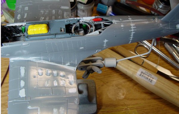
The footrest on the cockpit floor suffers from major divots. Rather than putty it all up, I just cut some sheet plastic to size and glued it right on top. The forward cockpit area got a coat of Alclad while the back deck area got a coat of custom Blue-Grey. The life raft was painted Testors Enamel Yellow with leather straps. The whole thing got a light black wash.
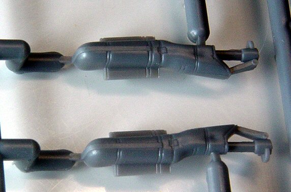
I would use good sharp snips or scissors to cut the side walls off the tree. Part #44 and #45 are very fragile. The oxygen bottles have an ejector pin mark right in the middle that need to be taken care of. A dab of putty and a few swipes with some sandpaper took care of it. The oxygen bottles got painted Testors Enamel Bright Green. Part #67, the button panel on the right, got a coat of Interior Black and highlighted with grey then glued to the right side panel.
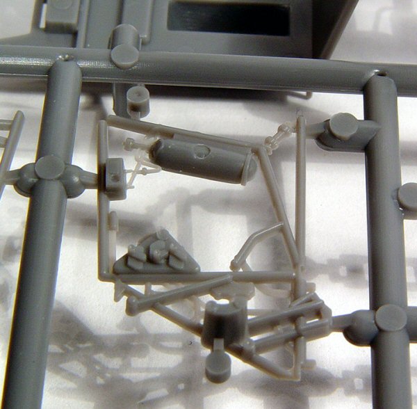
Part #46, the frame of the seat has small plastic passage plugs or “knock-out-tabs” that need to be carefully removed. This is another area that is real easy to break if you are not careful. I didn’t like the seat so I pulled a resin one out of the spare parts bin. It has over the shoulder harnesses and lap belts molded in. The shoulder harnesses might not have come on this plane at this time. Some planes were modified in the field but documentation on which ones were retrofitted is lost in time. I held off putting the in seat and the rollover cage until after painting to keep from breaking it off.
The RDF Loop Antenna is molded on the clear tree which threw me off for a few minutes. It got cleaned up and painted gloss black with the right half of the loop painted silver. This was common practice in that time period. I do not have any proof if the Midway planes had them painted as such. Another educated guess on my part. I did not install the antenna until later. It is just too easy to break or loose during sanding. Eventually it will fit into a recessed tray at the edge of the gunner’s position and is a good replication of the way the real one sits in the plane.
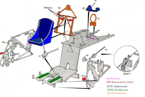
The side panels sit in small saddles on part #42. They do not have a solid feel when you put them there. Some other builders have glued them to the fuselage sides then when it is time to put the floorboard in they kind of hook them over the little saddles. Your choice. The side panels are rife with knock-out tabs. Make sure to carefully cut each one off. A small part #60 gets put on the left side panel. There is a detailed drawing on the right side of the directions that doesn’t really help in its location. I used superglue to put it between the two small prongs you will see and painted it black.
The control stick, part #43 got a coat of silver with black handle and leather for the boot which then got glued into the floorboard. I painted the push-pull rod that runs under the seat, a different shade of silver just for depth.
There is a note on the first page of the instruction sheet that reads something like this “The cockpit is composed of a lot of fragile parts. Do not lay the sprues flat to cut these parts off because they will very likely break. We strongly recommend that you separate these parts from the sprue with cutting pliers or a hot knife so as to avoid any unnecessary breakage.”
This is good advice! I wouldn’t use a hot knife because I think the parts are just too delicate and you could distort the thinner parts near the area you are cutting. A good pair of very sharp scissors or snips works well. You will see how fragile parts #51 and #50 are. NOTE: (Part #50 is not labeled on the instruction sheet)
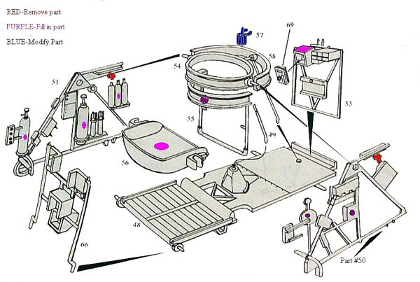
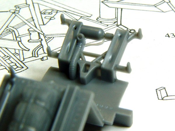
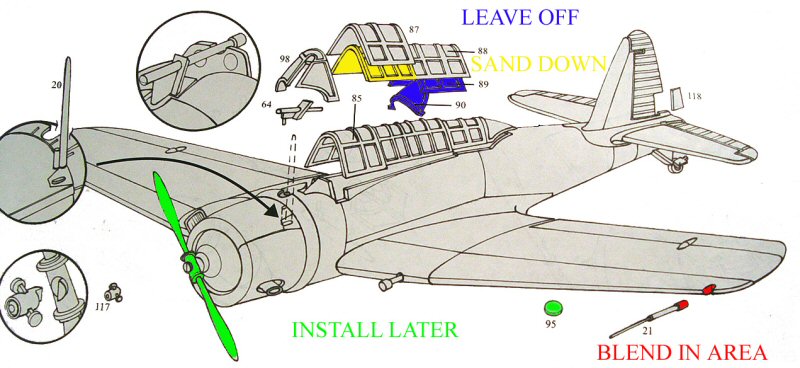
To prepare these parts for assembly, you need to cut off the knock-out tabs on both part #50 and #51, marked in red on the instruction sheet in this article. Fill in the ejector pin marks on the oxygen bottle, flares, and the pressure bottle on Part #51. On Part #50, on the handle towards the front and on the small box in the middle of the part, is another area that needs filling and sanding. I used dark purple to show the areas that need to be cleaned up but on the opposite side of the part and bright purple to show the facing side of the part that needs filling and sanding.
There is also a tricky ejector pin mark in the bottom of the gunner’s seat pan. I used a bit of sand paper glued to a piece of scrap plastic rod to get into the bucket and sand it down. Others might leave it as is and cover it with the photo-etch belts.
Part #53 has a large sink mark in the top of the com box. Fill that in and sand smooth with a sanding stick then glue part #69 onto the box. At this point everything got painted with Alclad Aluminum. I then painted the oxygen bottle the same Testors Bright Green that I used on the forward cockpit oxygen bottle. I used Testors Interior Black to paint all the boxes and handles along each side panel. The flares are painted a wood or tan color with dull silver fins on top.
There is an ejector pin mark on the inside of the gunners ring on Part #55 that needs sanding and then you can glue it into the main ring of Part #54. You will see a small tab that you glue part #58 onto.
Let this sub-assembly dry. It is very fragile and needs to be a solid piece before you can try to fit it into the cockpit area. This part will eventually be glued into the floor (Part #48) via a small rod protruding from the ring. The two side panels will give the gunners ring more stability before inserting it into the fuselage. I did not glue the ring tabs into the two side panels to allow me to adjust the parts better.
The seat hooks into the U shaped footrest easily. Be sure to put the seat above the small locating pins on part #55. The control stick can be installed at this time. I have heard that this stick was removed and stowed somewhere in the aft cockpit to be used only when needed. Stowing it kept it from getting interfered with during heavy maneuvering by the pilot and gave a bit more room for the gunner to move around quickly. Your choice.
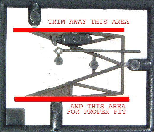
Part #66 does not have a positive feel to where it goes. The part just kind of sits on the top end of the floor, Part #48. Make sure it is at a 90 degree angle to the floor. Part #53 has a more solid feeling when installed because of the small trench it fits down into at the other end of Part #48. Part #57 is the mount for the gun. I do not understand exactly how it is suppose to work since you can not transverse the gun from the left to the right due to the ring mount pin. I have looked at a lot of pictures of this area and in hind sight I think I would have scratch built a better mount that allows the gun to be in the more commonly seen stowed position.
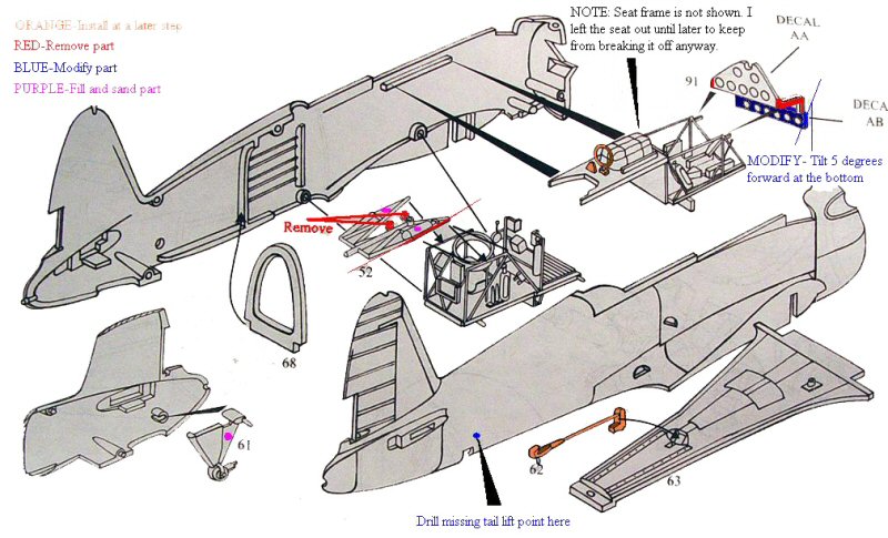
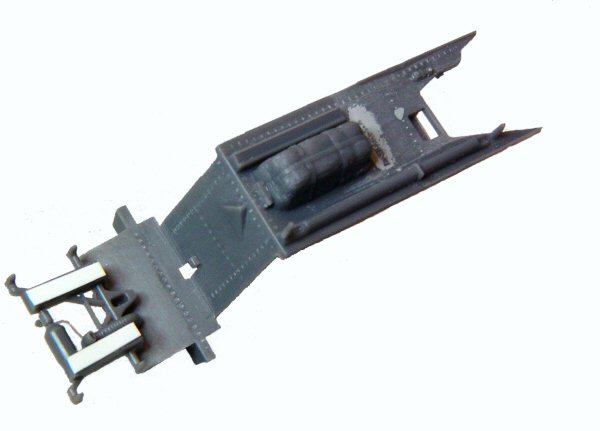
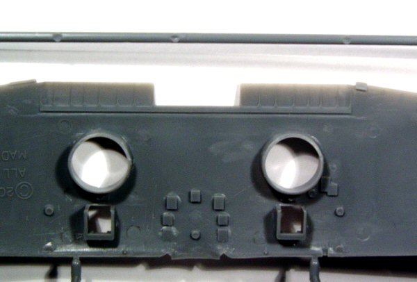
The whole aft cockpit sub assembly is also the part that sets the width of the fuselage halves. Part #52 needs to have the knock-out lugs cut off and the fire extinguisher bottle has an ejector pin mark on it that needs filling and a coat of Testors Bright Red with a chrome handle to really set it off. There are also ejector pin markings on the small triangle flat pieces on the top of Part #52. The right side and left side of Part #52 needs to be cut down a few millimeters. It causes a strange angle that forces the part out of alignment when it hits the upper fuselage halves. Refer to instruction graphic and picture for clarity.
Part #68 helps strengthen the fuselage halves and fits very well. I painted this aft area an off white to replicate the fabric surfaces then painted the stringers, stiffeners and Part #68, silver. You need to trial fit the aft cockpit area many times to include part #63 (bottom of the fuselage) to get the spread of the bottom of the fuselage right. Misalignment at this point will throw the wing joints, cockpit windscreen and bottom of the wing off. Take your time here!
The front cockpit gets glued in at this time. The instrument panel (Part #91 on the clear tree) was very difficult to fit in. It needed trimming on both bottom corner edges. The small panel below the instrument panel needs the bottom edge tilted up just a few degrees. The clear part is brittle so you will have to either cut it off and re-glue it or carefully bend it to place. I painted the panel flat black being careful not to get any paint into the instrument faces. The decals go on the backside of the glass. I did it with a layer of Future Floor Wax to slide them into place but the glass is so thick you really can not see the decal dials. You might want to punch out the decal dial faces and place them inside the front side of the instrument panel for a more realistic look. Again, trial fit the instrument panel because it will throw off the spacing of the forward fuselage and mounting point for the engine if you do not.
The tail wheel has an injector mark on it that is easy to clean up. There is a good strong lug on each side of the fuselage for the tail wheel to set in. It is very strong even though it looks fragile. There is a small tab on the wheel that replicates a tie down lug. You can either cut it off and replicate it with thin wire or leave it as is. I didn’t bother painting it because it will get a coat of light grey when the fuselage gets painted in the near future.
I use a very thin superglue to glue the rudder halves together. Sometimes hot glue will actually melt and distort the thin trailing edges. Accurate Miniatures did an excellent job on the thin trailing edges throughout this kit. The superglue prevents this from happening. Once the tail is glued together, I zipped up the fuselage halves letting the glue wick up the seams.
Part #63, bottom fuselage section, is a bit of a fiddly part. You have to get it to fit into the bottom tail area up to the fuselage wing root area. It doesn’t want to seat into the area very well. You just have to work it to its proper alignment. I got all the seams straight and the large underside of the fuselage to fit just right with some sanding and lots of clamps were used. I checked final fit before leaving the whole thing alone overnight to dry to make sure nothing would shift on me. The trim tab is molded separately and can be glued on anytime you want. I waited until I was finished sanding to keep my clumsy hands from knocking it off in the sink.
Fill in where the upper structure meets the two side panels on the gunner’s compartment and cut the V shape to a converging point in the fuselage. It is filled in where the fuselage halves diverge to make the aft compartment.


I held off on installing the cowl flaps but did glue the engine mount onto the closed flaps. The only reason I did not choose the open flaps is that there is some good detail not molded on the underside of the open flaps. This is not a bad thing. Many kits give you this option with no detail there either. It is totally your choice.
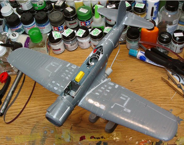
Now we tackle the infamous sink marks. I used Mr. Surfacer 500 to fill in each one along its stringer line in order to keep the shape in line. I used a flat sanding stick on each panel, one at a time and in about 20 minutes it was done. After cleaning up the fuselage seams on the top and bottom, I taped off all the metal surfaces and sprayed Mr. Surfacer 500 spray paint on the area to replicate the rougher texture of the fabric. It was an easy fix.
Some say that they should never have had to fix this problem on such a high quality kit and others say it is no problem fixing with just a little effort. After doing it, I think it really was no big deal. That is just my opinion. Yours could be completely different.
I am also trying a new technique out on this model of stressing the thinner metal panels so while I filled in some unintentional divots; I carved out others in the wing root area. More on this technique when we tackle the wings. One thing I will admit to right now is making a few mistakes. A few in research and a few in “I thought it would work”. Lessons learned. I will point out my mistakes and try to tell you why I did it and be aware of the trap.
I decided to build the engine cowling and then temp install it onto the cowl flap assembly without installing the engine. The cowl flap assembly gives the cowl some rigidity and shape during sanding. The cowling is split at the 1 o’clock and 8 o’clock position. The scoop is poised around the 11 o’clock position. This gives the cowl a strange lopsided oval shape when viewed from the back and a perfect circle if viewed from the front. This was a very difficult piece to mold and hats off to AM for tackling this part and doing it right. When you see the oval area slowly blend to a circular shape with a scoop in the middle of the blend, you will see what I am talking about and it will make sense why they molded it the way they did.
I glued the two cowl halves together carefully and while the glue was still a bit soft, I glued the front cowl ring on (Part #13) and aligned the cowl pieces off that. Once dried, I glued part #116 (inside scoop) into the top half of the upper cowling, part #115 and aligned the front edge of Part #116 to the front cowl to keep from sanding too much away. There is a graphic above the cowling drawings that really isn’t needed and a bit confusing. It tells you to remove a knock out tab that is not there on the piece and to sand the angles to the curve of the cowl and implies to do it before installation.
I then put the cowl on the cowl flap ring temporarily just to help the cowl keep that oval shape at the rear. The cowl ring will be pulled off again later and the engine will be put inside but not until after painting. Now that the whole thing is solid and the glue is totally dry, I sanded the pieces for a better shape all around. I did sand some of the detail off and needed to replace it and use a scriber to re-scribe the lost detail. I totally sanded off the strip of metal that the cowling pieces fasten to on the real thing. I replaced it with some strip plastic, sanded it down to scale and re-scribed the fasteners on it. Not perfect but not bad.
The engine is a real gem in my opinion. The front crank case looks spot on. I painted it a dark, almost gunship grey color and did a dark wash to bring out the detail. Brass wire harness and bronze sparkplug wires. The cylinders got a coat of black with Old Silver fin detail dry brushed on. The same gunship grey color was used for the rocker arm covers. Most of that upper detail gets hidden in the cowl but hiding detail is nothing new to us. Check out Accurate Miniatures TBD Avenger. Now there is some hidden detail!
The cowl mount (Part #10 or #9 if you want the open cowl flaps) glues to the engine mount (Part #14) uniquely but it works just fine. The engine is a simple sandwich style we are all use to seeing. Here is where I made another mistake. I totally forgot to put Part #19 (the propeller shaft) through the crankcase nose. It is not numbered on the instructions sheet but I have been around models and the real thing long enough to know this was suppose to go on at this point. This mistake will come back to haunt me again later.
I committed another mistake with the exhaust at this time. I looked at the two exhaust stacks and the tips were not completely formed. I wanted to replace them with brass tubing but did not want to do it at this time. I should have put some small flat pieces of sheet plastic to glue the stacks onto inside the cowling but forgot.
But I did remember to cut a small oval to place the large antenna into on the top of the cowling. It is not marked where the antenna should go so I had to check my reference material to make sure it was spot on. I glued some sheet plastic inside the cowling to give the antenna something to mount to. The finished engine looked wonderful and the cowling didn’t look too bad either. The pieces got put off to the side for later installation.
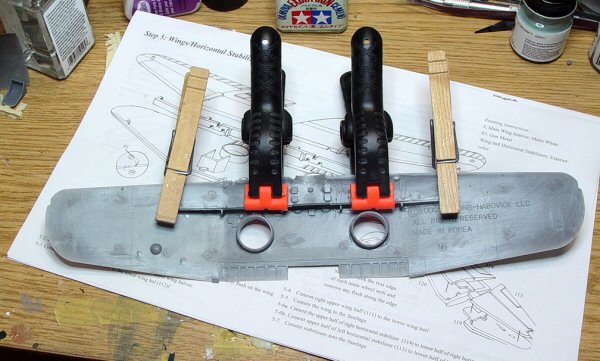
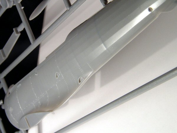
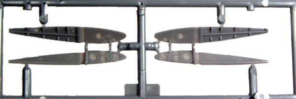
Now for the wings. It is a one piece bottom with a great I-beam construction and two top wing skins. Simple and strong. Now for some more work. The bottom wing warps downward past the injection lugs on the front edge. Not a big deal in that the I-beam straightens out the sagging wings. I used some spring loaded plastic clamps and cloths pens to get that I-beam perfect. The bottom wing has some great detail in the flaps. The top wing panels also have great detail in the flap well. Almost all the photos I saw show the flaps in the up position but it is real tempting to cut these open and show this hidden feature.
There is a mystery here in that Accurate Miniatures included a super set of wing folds, Part # 6 and Part #7. These parts are great but I don’t think they can hold up an outer wing panel by themselves. A little brass tubing and some detail could make a wonderful wing fold brace. The Squadron In Action has a great drawing on how to do this. Now for another mystery. There is no line to scribe on the inner wings to cut them apart. It is not a big deal to use the panel lines on the outside of the wing but it sure would have been nice to have this area a bit thinner. I think one of these with a folded wing would look great next to say a Monogram Devastator with folded wings. Especially if you are doing a golden wings SB2U-1. I can tell you that when I do my -1, I am folding the wings.
Another bit of controversy is what should the guns mounted in the wings? This is a bit dependent on exactly which aircraft you are modeling. The SB2U-3 had provisions for 4 .50 Caliber machine guns. The Marine Corp normally only carried one gun in the inner starboard (right) wing. Were the empty wing holes covered over with tape? Sheet metal? And what about the shell ejection ports? Covered up with tape? Sheet metal?
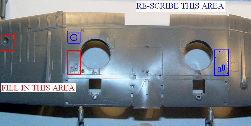
Here is the main problem with the AM wing. It has a nicely done shell ejection slot only on the inboard Port (left) wing machine gun position. There is nothing on the Starboard side inboard or outboard where the other two machine guns sit. My educated guess is that they had sheet metal covering the unused openings on the underside of the wing and leading edges. I missed it totally in my build. I would re-scribe the missing ejection ports onto the Starboard wing and fill in the port wing with some very thin plastic sheet to simulate the covers. I would also fill in the wing leading edge for the other three unused machine gun barrel ports.
There is also a problem with the landing light. It should be filled in and replaced closer to the right side of the wheel well. This is not a big deal in modifications. You can build up a block of plastic on the back side of the wing then drill into the wing from the outside to get the concave shape and depth. Just don’t drill too deep. A quick scribed square around the light hole with some fastener detail and you are done.

Like the rudder and tail, I used thin superglue to keep from melting the thin trailing edges with liquid glue. Once dry the wings are extremely strong. Now I worked on the Stressed Skin technique I have seen on some aircraft. It really adds a lot of realism to the subject. I drew lines on the wing with magic marker where the structural sub-members would be. Don’t worry about marking up your plastic. It will all be sanded and polished off.
Once this was done, I took a curved #22 carving blade and graded off some of the plastic between where these sub-structures would be, replicating the thinner metal being slowly bent in due to foot traffic and high g factors of pulling out of dives. This got a very thin coat of Mr. Surfacer 1000 and sanded out.
I then took my pounce wheel and put down tracks where rivets would be. Then the whole thing got polished with a variable speed Dremel tool and cloth buffing wheel and some Tamiya polishing compound. If you use this technique, you need to make sure to not apply too much pressure or have the Dremel set too fast. You can melt the plastic easily. This will set up a whole bunch of new problems. The final result is much more subtle than you would think. After a few layers of paint, it is not as dramatic as it looks in the in-progress build pictures. I will talk about painting and chipping these areas later.
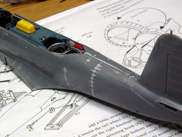
I think the fabric tape along the wing ribs is overdone. I knocked it down a bit. No big deal but it does improve the look of the wing in my opinion. When I glued the wings to the fuselage, the right wing root had a millimeter wide gap that had to be filled with strip plastic. It got filled in with Mr. Surfacer 500 and sanded down. The wing roots got the same stressed metal treatment that the inboard wings got. I also did this to all metal surfaces on the fuselage and leading edges of the wings. It was time consuming but really adds a lot to the finished product. The bottom of the wing where it meets the fuselage doesn’t meet flush. This would not be a problem at all if you drop the flaps but with the flaps up, it needs to be trimmed out a bit. You will see what I am talking about when you put the wings on.
The front edge of the wing root where it meets the fuselage needs a bit of filling and sanding. You can glue in the glass panel at this time and put the mask on it to protect the clear areas. You will not remove these masks until all painting is complete. The glass panel is a tough fit and you might need to do a bit of trimming on the fuselage opening.
The elevators were no problem at all in fit. It did take some filler to blend them to the fuselage but nothing you would not see on any other model. Everything got sanded down and polished. A layer of Mr. Surfacer spray paint gave a good primer coat.
Now I installed the engine/cowling, adding a bit of brass rod for the propeller shaft that I had forgotten earlier in the build and turned my attention to some of the other little bits and pieces. The pitot tube has a large area to be plugged into on the wing but the tube itself is of a smaller diameter. I used the kit pitot tube and some more filler to clean up and blend in the area. You can use some brass tubing or hypodermic needle if you wish to spruce up this area.
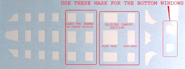
At this time I glued the bomb trapeze into place and the floor window that goes right behind the bottom of the cowl. The glass needed just a bit of trimming with a sanding stick to fit but almost snapped into place under the fuselage after trimming. I used the kit supplied masks to cover the clear panels up for protection from paint and scratches during construction. Rare pictures of White 6 show the 100lb bomb shackles that were mounted on the wings but with no bomb attached. I cut the 100lb bomb off the racks and cleaned up the seams and glued them on.
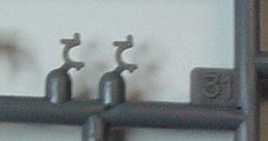
There are two small “C” shaped clamps (Parts #31) that are installed on the wing inside the notch at the top of the wheel well area. I think that they are supposed to lock the gear in the up position on the real thing. The instructions do not clearly tell you if the “C” faces inward or outward. The correct answer is that the “C” should face inward on both sides. I am still not sure how the real thing works. I think linkage moves it out of the way during full retraction and spring tension allowed it to hook over the strut when the gear is in its full up position.
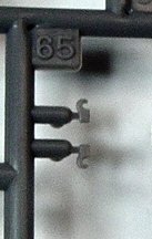
Adding to the confusion, the directions have the catapult cable hooks labeled as Parts #31 and the previously mentioned gear hooks as Parts #65. This should be just the opposite. I didn’t notice it at first and ended up ruining the catapult hooks. I replace them with some extra resin pieces from the spare parts bin and now you can not tell the difference. Remember on the “Gear Up” option Parts #31 are not used.
The bomb mount got cleaned up and fit really nicely into the bottom of the wing. It only goes on one way and is a strong little piece. It will get detailed out with black and umber washes later simulating engine oils hitting that area hard.
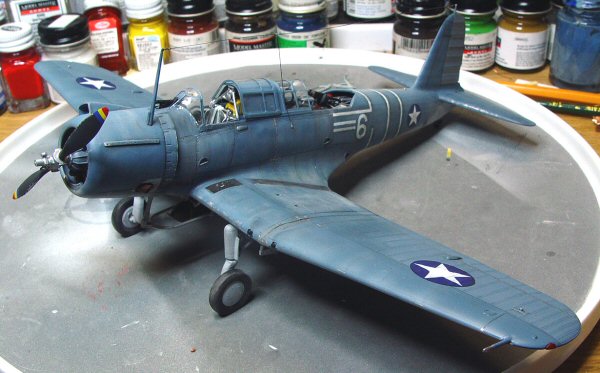
Now the plane is ready for paint. I used a stiff bristle brush and some Mr. Surfacer 500 to replicate the roughed up areas on the wing walks. This adds texture lost during sanding and blending of the wing root. Then during the pre-shading paint session, I painted these walk areas. After drying over night I used some Tamiya low adhesive tape and cut it to width and taped over this area.
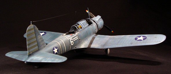
I have spent a lot of time watching John Ford’s film on Midway featuring a few great shots of White 6 in color and studying any pictures I can find on the subject. Like others before me, I have come to a few conclusions. The bottom of the outer wing panels are not painted the same as the top color of Blue-Grey. They are painted light grey. The same color used on the fuselage and center wing area.
I used Testors Model Masters Light Grey (FS 36440) for the bottom and a mixture of home brew Blue-grey starting out with Testors Dark Blue and adding the same Light Grey to get the mix right. Once the fuselage and wings got sprayed the Blue-Grey concoction, I lightened up the color and went back over all the fabric areas with the lighter mix. Fabric always seems to fade faster than the metal surfaces. It also gives the two tone paint some depth, character and distinction.
Now comes the artistic part of our hobby, the layering process of light and dark tonal changes in high wear and low wear areas. You have to take into account the harsh conditions on Midway. Salt water, no hanger and relentless sun took its toll on the paint quickly.
The light grey underside got sprayed on everything down there. Wheel wells, bomb racks, etc, it all got painted light grey. The demarcation line between the two colors should be a real tight pattern.
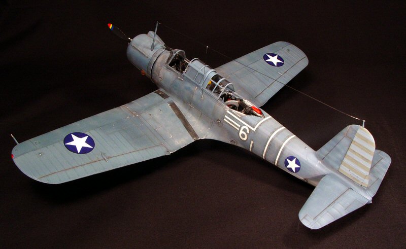
After all was completely dry, I removed the walk wing tape and gave the whole plane a coat of Future to get it prepped for my favorite part. The decals! The Stars on the top of the wing should be the 41 inch smaller wing stars and not the larger 60 inch pre-war stars. I robbed a set from a Super-Scale P-40E sheet I had left over. Accurate Miniatures gives you the option of putting the red dot in the middle of the stars then a small white disc to cover the red. I painted a very light red almost a white with a hint of orange to replicate the painted out red dot.
There are no good pictures of the port side of the Midway Vindicators so your guess is as good as mine. I tried to keep it symmetrical but who knows. Depending on the plane you want to model, each set of white stripes are different. As is well known, the white stripes are medical tape used to keep the fabric together until the planes could make their way to Ewa for refit after the battle. None of the planes made it. Only three survived the battle and were scrapped on Midway.
You can think ahead and paint this area white then just use small strips of masking tape to be pulled off after painting the main colors or use small strips of white decal film. This is what I did. The medical tape was doped over to give it some strength but this discolored it and the surrounding paint a bit. I used Tamiya Smoke to replicate this to great effect.
After attempting to paint the over painted stripes on the rudder, I decided to use the rudder decal that replicates the painted over red and white stripes. The decal did not want to snug down and I had to use extra coats of Solva-Set. Make sure if you use a hot emulsifier like Solva-set, let the decal fully dry before applying more.
This is where I dropped the model and snapped off the rudder antenna mount. I had to make another one from scratch. Not a big deal but it was extra work I could have done without.
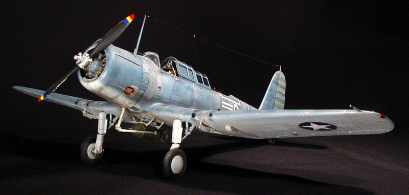
Now that I finished the decals, I wanted to finish the landing gear to get the plane sitting on its own legs. This is always a favorite part of the build for me. Accurate Miniatures gives you two choices on your landing gear. In the “Gear Up” mode, you can use the un-weighted wheels and gear specially molded in the gear up position. Or you can use the more traditional “Gear Down” mode, where you can use the weighted wheels. The center part (Part #34, 35) of the “Gear Up” configuration have heavy sink marks on them that need to be filled if you are going to use this option.
In the “Gear Down” configuration you get two nicely rendered but spindly landing gear struts. After putting the small scissor linkage (Part #32, 33) on the back side of the struts, paint the whole thing the same color as the bottom of the wing. I used a dark oil wash to get the detail to pop out before installing the other pieces.

Think about each gear piece being a little model in itself. Look how the parts are built, where they go and how the weight of the model rest on them before touching glue to plastic. There is a pair of over-center linkage (Part #26) and another locking mechanism (Part #28) that rest on the spring strut inside the wing. This is a very hard piece of engineering to explain and even a harder one to draw for the instructions.
The spring strut cleans up very well. I painted mine flat black and then dry brushed silver onto the coil of the spring. I then glued it into the small tab hole on the main spar of the wing. Then place part # 28 against the front part of the wheel well. The spring strut will rest in between the locking mechanism. Let these pieces dry firmly before continuing. The next piece will be the over the center linkage (Part #26). The bottom end will fit into two small tabs on the top edge (remember the wing is upside down now) of the wing spar. Then the other end will go into a notch on the gear strut. I used liquid glue to get the part straight and aligned with the other side.
The gear strut covers, known as the knee caps, glue straight onto the strut with the top of the cap touching the bottom of the wing. You don’t get a good feel for where they go so just place them onto the strut and get them lined up. They will look just fine when finished.
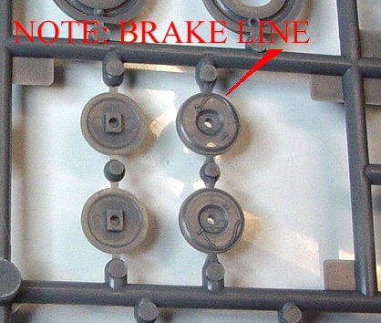
The two wheel halves glue together with no problem. Some sand paper takes care of the seam quickly. The inner brake disc should be oriented to have the break line molded to the face of it, facing towards the wing. It might be better to sand this smooth and replace it with some wire. The face of the wheel (Part #27) fits like a glove. Another light wash of black really brings out the details in the gear. I assembled the wheels and placed them aside until after painting.
I used a spare 500 lb bomb from a Hasegawa P-40E to replace the 1000lb bomb that came with the kit. I used Bare-Metal-Foil for the bomb ring and some plastic rod drilled through the bomb for the hanger pins. The Marines at Midway did not have 1000lb bombs nor did they have the 100lb bombs out on the wings. To make up for the underpowered aircraft, the Marine Corp limited the Vigilante to a 500lb bomb load. Accurate Miniatures gives you two external fuel tanks. If you use the external fuel tank then you should use only one in the center bomb rack. The two tanks are another one of the mysteries of this kit.
Next thing on the topside was the diving periscope. I drilled out the ends and used a drop of Future in each end. It got a coat of flat black and glued into place right over the center line of the fuselage resting on the instrument panel.
The propeller got a coat of Aircraft Interior black and then one by one I painted the Blue, Yellow, Red stripes on the tips. Glue the (Part #117) counterweights on the center of the prop hub and then paint silver. Like the wheels, I put this part off to the side to be installed after painting the plane.
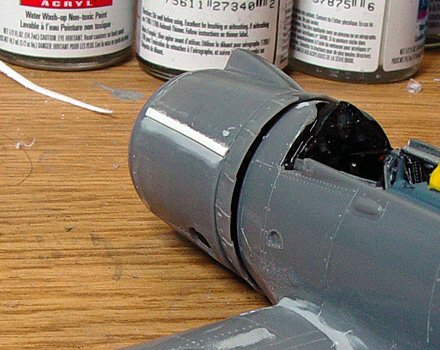
The glass was very brittle. I suggest cutting it off the tree with a hot knife and then cleaning up the stub with a sanding stick. Once I installed the glass, it was obvious that the front windscreen Part #98 did not fit well. I was stumped. I had already painted the kit and the windscreen and there was a large gap at the bottom of the windscreen. I ended super-gluing the glass on and used Mr. Surfacer carefully layered into the gap until it is filled in.
I took a very small piece of sand paper and slowly sanded the area smooth then went back and taped off the area and re painted it. I didn’t discover how bad this fit was until after I had put the large antenna on the engine cowling. It was difficult not to break it off. If you look closely you will see the mismatched paint which isn’t always totally inaccurate. This area got exposed to high heat for long periods of time from the inside so they might discolor at a different rate than the rest of the fuselage metal areas. Sounds plausible to me!
Then I used the mask to cover the window. The fit of the mask was off on almost every panel. I would still use it on the main windscreen but I think I will use the old “Tape off the vertical lines and paint, then tape off the horizontal lines and paint” method of doing large greenhouse canopies. Montex Plastic Model Club has made a set of mask that not only mask the outside but also have a smaller set to fit on the inside of the canopy frame.
There is a bit more confusion on painting the canopy solid right behind the pilot. There is indeed a canopy frame on the area right behind the pilots head. It looks like they just used sheet metal instead of glass on this area. I knocked down the canopy frame just a bit to help the sliding canopy fit over it and give it a more realistic appearance. I then lightly used my pounce wheel to restore rivet detail to the framing.
Part #89 and #90 should fit inside of each other and should fit inside of the main greenhouse part of the canopy right over the ADF loop antenna. The canopies are just too thick to get it all tucked inside. I ended leaving it off. If you have access to a vac-u-form machine then the best bet is to make a new one out of the solid (Part #85) closed canopy option and cutting the pieces apart. Trim them to fit and install them under part #88. Again, this is what I plan on doing on my next build.

The propeller got glued on after finding a small scratch of brass rod to replace the shaft I forgot to install earlier in the build. Remember that? The landing light lens got glued to the bottom of the wing.
I used some black scratch plastic, melted then stretched thin to replicate the antenna wire. It makes a very realistic antenna and can be easily glued with superglue to the aerials.
The machine gun got detailed out using flat black and then using a light dusting of pencil lead to give it that gun metal look. Small dark wood handles were painted on and a small photo-etched fold down gun sight was installed from a True Details set. On hindsight I wish I would have spent some more time on the gun but the build was starting to wear on me.
Conclusions
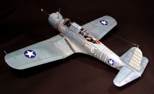
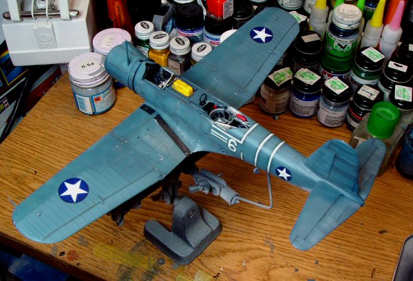
I sat back from a long build and looked at it. I was pleased. It sure looks like a Vindicator. I have to think back to the beginning and say to myself “Was it worth it?” The answer is YES. Then I asked myself “Should I have had to do that much work to get a passable model?” The simple answer is “No”. Most of these problems should never have happened. The modeling world howled when the blemishes of this kit were exposed. They did the same thing with Trumpeter’s Wildcat and look what that company has produced lately. The only thing I ask you to remember is that these companies are ran by people who truly care about the hobby and giving us the best that they can.
Well, Accurate Miniatures is a bit of a victim of its own successes. They came out of the chalks running at full speed. And they hit their peak with the brilliant SBD and some say the best plastic ever made with the Avenger.
The Vindicator did not live up to this extremely high standard Accurate Miniatures themselves set but neither did the Hasegawa’s Spitfire Mk1 or the HobbyCraft P-40B. I know for a fact that Accurate Miniatures does not have the resources of Hasegawa or Tamiya.
Face it, ALL of the major manufactures have had misfires. Some of them can not be corrected at all. This was just a little stumble from a great company that still has lots of leg left. Would I build another one? You bet ya! By the end of this year, you will see a Chesapeake and a -1 yellow winged Vindicator keeping company with my -3. Will I continue to support Accurate Miniatures? Whole heartedly! I expect great things from this company in the near future. I already own about 95% of every thing they have ever produced.