


Kitty Hawk Models 1/48 F-35B Lightning II Quick Build Review
By Michael Benolkin
| Date of Review | October 2012 | Manufacturer | Kitty Hawk Models |
|---|---|---|---|
| Subject | F-35B Lightning II | Scale | 1/48 |
| Kit Number | 80102 | Primary Media | Styrene |
| Pros | First kit of this subject | Cons | See text |
| Skill Level | Experienced | MSRP (USD) | $59.95 |
Background
For a brief discussion of this subject and a look at this kit out of the box, look here.
The Build
Note: I initially started this build as a full-build review and painted portions of the model accordingly (see narrative below). When I ran into some challenges, I ceased the painting and finished this model as a quick-build. I didn't use any fillers in this model's construction so you can see how well the model fits together. I've documented the glitches I encountered and how I worked through them in this build.
Note: You can click on any of these images below to see a larger image.
Before I got underway, I was trying to sort out which parts tree was A, B, etc.The diagrams at the front of the instruction booklet help, but once you start removing parts, none of the trees will look like that any longer. Kitty Hawk didn't put a tab in a corner of each sprue tree with a big 'A' (or whatever), but if you look closer, you'll see each sprue tree does have a small tab with a serial number on it and each serial number ends with a letter suffix. That suffix is your sprue tree identification (A, B, etc.)
I started by test-fitting the main fuselage parts and was pleased with the overall fit of the model though there are touches of flash here and there that need attention before assembly. There is also a phenomenon where some stubs have been pulled out of the parts where the ejector pins pushed the sprues out of the mold and these are simply snipped off with a sprue cutter. The most unique problem were the high-pressure air pins that are also used to remove parts out of the mold. The fuselage halves had the tell-tale 'nipples' left over that needed to be removed.
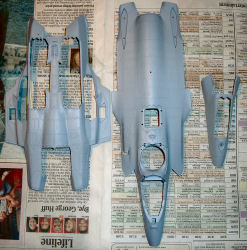
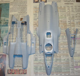
After initial clean-up of the major components, I applied Tamiya Primer out of the spray can on all surfaces that may be exposed to lacquer. Since the model is molded in a very dark gray styrene, the light gray primer also helps you to spot any imperfections, flash, ejector marks, etc., that need attention.
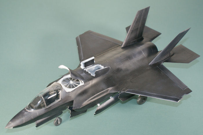
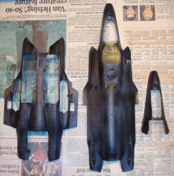
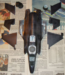
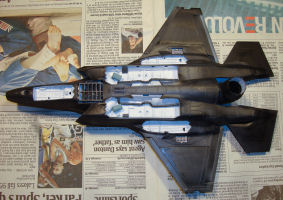
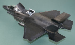
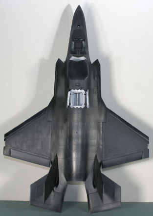
The next step was to paint all of the wheel wells, weapons bay, intakes, ducts, etc., Tamiya Flat White. I was a bit surprised how much of this model is white when I finished! When this had dried, I masked off the lift fan duct and auxiliary intake and applied Alclad II Gunmetal to all the exterior surfaces. This looks black in the photos and it is too dark for the finish of the aircraft, but there are a few more steps to the finish as we go forward.
Step One: The cockpit went together with no problems though the ejection seat needed a little tweaking to get it together. Like the nose wheel well, I didn't worry about painting the sub-panels on the side consoles. The ejection seat does need seat belts and shoulder harness detail even if they too are black. I'll address this in the next build.I never did find parts E28 nor E29, the side stick controller and throttle. It wasn't like they had fallen off the sprue tree, there were no part numbers 28 or 29 on tree E. I waited to the end of this build-up to go back and look through the 'spare parts' to see if these were mis-labeled, but no luck. Thanks to Richard Denby who've found them at G21 and G22.
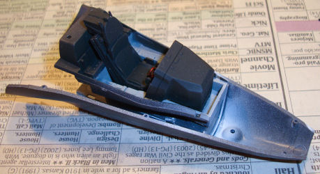
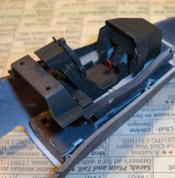
Steps Two and Three: The nose wheel well and cockpit were assembled per the instructions. The cockpit tub mounts atop the nose wheel well and both sit inside the lower nose half. As I was test-fitting the nose wheel well together, I noticed that while Kitty Hawk had done some nice engineering to try and make this kit fool-proof, some of the parts simply don't fit as-molded. After a little trial and error, I trimmed a few tabs and widened one slot before the well went together as intended.
You'll note that I haven't painted any of the details inside the well as I'll be doing this project as an experiment and I'll build another with all of the details brought out in the future.
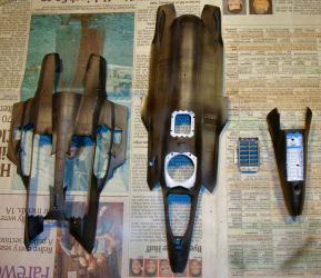
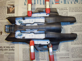
Here are the major airframe components with the first dose of post-shading that will lighten up the airframe color a bit. The ventral lift fan exhaust duct is painted with Alclad II Steel. By the way, the lower nose half with the cockpit assembly installed dry-fits beautifully into the upper fuselage half.
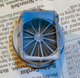
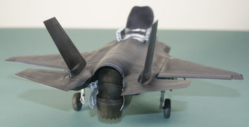
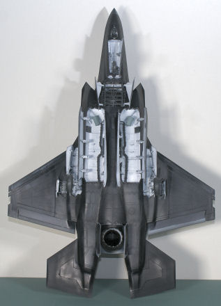
Steps Four through Seven: Take a look at that lift fan. This is the view from the bottom and the upper view looks just as great. The stator vanes are painted Alclad II Aluminum and the fan blades are painted Alclad II Magnesium. You don't see the contrast that well in these photos, but it looks great up-close. The engine is also nicely done. There are no parts for the accessory packs nor other external details aside from the structural web around the engine case. The compressor and turbine faces look just as nice as the lift fan. Kitty Hawk didn't waste effort with adding details where you will never see them. As you can see, the compressor is visible through the dorsal auxiliary intake and the turbine face is visible through the afterburner nozzle. Oddly enough, there is no afterburner spray array/flame holder detail in the afterburner section.
Another problem appeared at this point. The drive shaft for the lift fan is supposed to mount onto a corresponding tube on the fan assembly. The shaft doesn't fit. Not even close. I used a grinding bit in my Dremel tool to open up the inside of the shaft and to reduce the diameter of the mounting tube on the lift fan assembly. Now it fits...
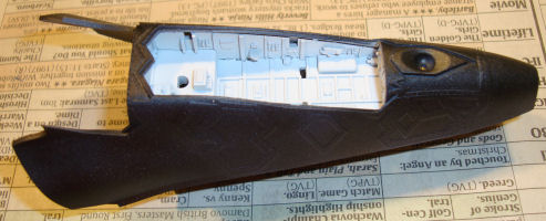
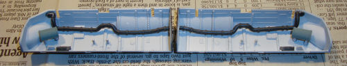
Steps Eight through Eleven: Here are the weapons bays. The black ducts have two tabs that mount into corresponding slots on the ceiling of each bay - the problem is that there is only one slot per bay. I eventually removed the extra tab from each duct and mounted them as you see here. Another problem is with the instructions, the parts numbers are wrong for the weapons bay ends - it recommended the starboard end for the port side bay and vice versa. If this were the only bug in the instructions, this was easy enough to sort out, but there are more to come.
Steps Nine through Thirteen: Here is where Kitty Hawk's engineering really shines. If you look in the dictionary under 'trying to fit ten pounds of _____ into a five-pound bag, this could be the example but Kitty Hawk does it (as long as you've applied your modeling skills correctly. Here is where even a single sprue stub that wasn't removed from a part will interfere with this assembly. This is going to be a tight fit.
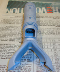
First, install the weapons bays into the lower fuselage half. These fit nicely. Once again, make sure there are no surface blemishes on the weapons bay surfaces that aren't seen after installation because next we install the main wheel wells over the weapons bays. I've got these clamped into place as the glue dries. The engine and lift fan assembly goes in last and make sure the troughs on the front end of the weapons bays are free of blemishes as well as the intake ducts themselves as these lay down into the weapons bay troughs.
Steps Fourteen through Seventeen: Here's the true test of Kitty Hawk engineering - getting the upper fuselage half over all of that stuff in the lower half. When I did all of my dry-fitting of parts, I was able to mitigate in advance most of the fit problems one might encounter at this point but I now have some additional lessons learned here. The kit instructions would have you glue the lower nose half onto the intake ducts before adding the upper fuselage half. I opted to wait on this until the lower fuselage half was in place first. This allowed me to see more inside the fuselage from front and rear for any clearance problems as the fuselage halves went together.
The engine has three stubs that mount to the lower fuselage half and in this build, I used glue to keep the engine assembly in place. The upper fuselage half mounts onto the two stubs atop the engine. As I pushed the upper fuselage onto the engine stubs, I had to 'massage' the kit together. The one part that needed to be seated was the upper lift fan shroud into the corresponding hole in the top of the fuselage. If you look close to the image below, the auxiliary intake opening didn't line up completely with the corresponding opening in the top of the fuselage. This turned out to be the only glitch and I was still able to glue the upper and lower fuselage halves together.
The lower nose half went snugly into place but the two mounting stubs in the upper fuselage half that attach to the two holes in the rear deck of the cockpit would no longer line up. I simply removed the two stubs and glued the lower fuselage half into place without further problems. This challenge isn't a problem with the kit but with the fact I assembled this out of order.
I assembled the wing halves as well as the stabilators and vertical stabs per the instructions. It took some time to trim and dry-fit some of the lower-surface inserts in the tail feathers to get them to fit but this was worth the effort. The wing halves actually don't touch one-another until out near the wing tip. There is a visible gap between the wing halves for most of the wing span to accommodate the long tabs on the leading and trailing edge flaps with only three mounting tabs to hold the wings together. As it turns out, this will come in handy in the future.
When I did assemble the leading and trailing edge flaps in steps 16 and 17, I found that the instructions recommended the wrong parts. Don't worry, just be skeptical and dry-fit everything. This wasn't rocket surgery (or brain science)...
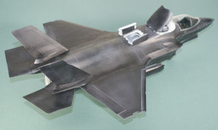
Step Eighteen: So here is where this build went from a full-build to a quick-build review. When I took the assembled wing (sans flaps) and dry-fit it to the assembled fuselage, I discovered something I'd never seen before. The lower fuselage half has female mounting holes for the wings as shown in the image below. The problem is that the corresponding points on the upper wing halves are also female (what do they call that female-to-female mating thing again?) and as a result, the join doesn't work as it alters the wing thickness at the wing root nor provides any mechanical retention to hold the wing onto the airframe. I removed the female mounting holes on the wings and dry-fit a wing again. The gap needs to be as high as the female mounting holes are on the lower fuselage halves to achieve good alignment.
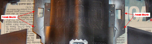
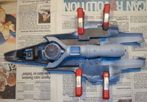
I used a liberal amount of liquid cement to press-fit the upper and lower wing halves to their corresponding edges on the fuselage to obtain enough strength to hold the wings in place. While this approach worked, the alignment was still not correct, hence the downgrade to quick-build. Based upon this experience, the solution is simple enough (see the recommendations below).
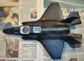
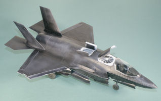
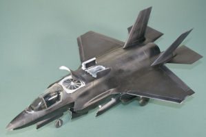
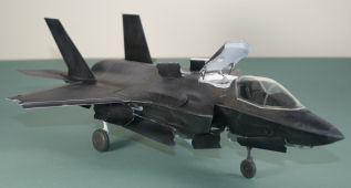
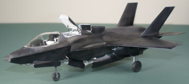
You can see in the images below that the aircraft is starting to look like an F-35B. The vertical stabilizers and engine exhaust duct/afterburner nozzle are dry-fit for these images.
Steps Nineteen through Twenty Four: Here is where we start installing all of the various doors and their hinges. First I installed the landing gear as I'd add these right after painting the airframe which was the original plan for this build. Note the small weapons bay insert doors and those frames, the bottom edge of each frame is actually a mount for a missile rail - Kitty Hawk did indeed add the weapons bay missile rail mounts in this kit. No rails are provided here but this is easy enough to fix just like adding the weapons suspension systems in each bay for the JDAMs (or whatever your favored loadout might be).
Note that when you remove each door from the sprue tree, if it has the hinges molded in place, cut them first to avoid breaking them when you cut the sprue tabs on the doors themselves. For the doors with separately molded hinges, these all fit nicely but you'll have to pay attention that they all align perfectly so they'll engage the corresponding mounting holes in the airframe without any problems. The only glitch here were the outboard weapons bay doors - there are four separately molded hinges per door and the instructions mixed up part numbers again. I wound up mixing and matching hinges until I got the right hinges in place (most of them are nearly identical) and they aligned correctly. This was just a few minute process that gave me flashbacks to my Air Force mechanical aptitude tests many decades ago.
Conclusions
This kit is a diamond in the rough. There is lots of great engineering and some unfortunate blunders all mixed together. The instructions really need to be tested thoroughly before a kit is released as ALL of the errors could have been detected and fixed in advance. Is this kit suitable for Tamiyagawa modelers? Nope. If you're a proficient model assembler, this kit isn't for you, but if you do have good modeling skills and experience, this project isn't difficult (I built it). Just take note of the points I raised here and go into this project skeptical of the instructions.
Things I'd do different:
- Mount the assembled lower nose half to the upper fuselage half before adding the lower main fuselage half
- Do not glue the engine subassemblies together as shown in the instructions:
- Build the ducts, lift fan, engine, nozzle/afterburner, and drive shaft separately and set them aside
- Mount the engine to the upper fuselage half
- Mount the ducts to the engine and align the auxiliary intake before gluing
- Dry-mount (no glue) the lift fan drive shaft to the engine through the intake duct hole
- Install the lift fan assembly to the upper fuselage and drive shaft
- Install the main wheel wells and weapons bays into the lower fuselage half as shown in the instructions
- Assemble the wings per the instructions but wait on leading and trailing edge flaps
- Remove the wing-fuselage female mounting points from the wings and fuselage noting the thickness of the mounting points and replace with strips of Evergreen styrene
- Install forward and rear wing spars made from Evergreen styrene strips into wings, staying clear of flap mounts and ventral roll vents
- Install spacer of the same thickness as spars on lower fuselage wing-fuselage mounting point between the spars
- Dry-fit everything frequently and when you have a good mechanical wing fuselage joint, glue the fuselage halves together and install the wings
- An alternative to the spar approach is to mount alignment tabs alternatively on the wing and fuselage so they dovetail together, on both the upper and lower surfaces, so the wing/fuselage join is perfectly aligned
So the real question is: Would I build this kit again? Absolutely. In fact I want to do another F-35B before the F-35A is released to verify the above steps and this time finish the paint job that I'd started here. The other thing to consider if you should build one is how to pose your model. I did this one per the instructions (with the exception of leaving the canopy open) but with the exception of some unique combination of maintenance actions or a special photo shoot, you'd never see the engine configured for VTOL, the canopy and weapons bays open, the leading and trailing edge flaps up, and the stabilators neutral.
When the nozzle is full down for vertical flight, the stabilators are also set to nearly full pitch-down just like a Blackhawk's stabilators in hover. The flaperons are also set down as well. With the included pilot figure, you can set up this model to depict it just as it plunks down on landing.
I'm torn between posing the aircraft in pre-flight with the lift system closed up, nozzle full up, canopy open, and weapons bays open; or posing the aircraft for a short take-off from a flight deck with the nozzle at 45 degrees (which will take a little surgery), flaps down, weapons bays closed, lift system open, and canopy closed with the pilot strapped inside. The kit as-designed shows off all of the features at once but it has lots of potential to render a number of different configurations.
Recommended for experienced modelers.
My sincere thanks to Kitty Hawk Models for this review sample!